A friend of the family suffered from a stroke which left him unable to use one side of his body. We went looking for a controller that would allow for one-handed operation of an Xbox One. He is a bit older so he never played any current video games, but if there ever was a time for learning anything new… I looked around at what was available for single-handed operation of Playstation or Xbox consoles, and was a little disappointed in the results. Probably the best overall is Ben Heck, who does engineer these units and sells them for a very modest price to help people with disabilities. In fact, much of Ben’s post was used to inspire and influence the design of this device. However, I don’t think that the design posted on Ben’s site is very user-friendly. A better design would be to graft the Xbox one logic onto a joystick. Basically replacing the left thumbstick with a joystick. I think that you will agree that this is a better design. I will be developing this as a I progress in the project.
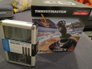
First off we will need some parts / tools. I chose this Thrustmaster flight stick since it was cheap an had enough buttons etc too look like it would work. Also we will need a set of specialty drivers since the Xbox uses some funky tamper-resistant screws. The Macro Bit Set from IFixit has all of the necessary bits.
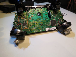
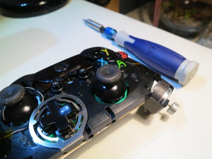
Remove the front and back covers. Back wing covers just snap off with a little coaxing. Then there are 5 security screws which allow removal of the rear shell and access to the boards.
Remove rumble motors. These need to be detached before the boards can be removed from the shell. I am not re-using these so I just clipped the leads off at the board.
These few websites give a detailed explanation of the board layout, what buttons go where etc… Take a look to familiarize yourself with the info. I am not going to re-create this info since they already did such a good job of laying it out. The subsequent images will just be an overview of how I wired the system up. It should make sense if you have read / watched these links.
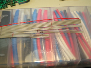
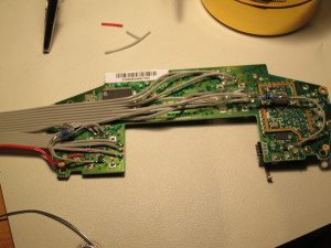
Separate ribbon cable with a razor. Be careful not to nick the copper core, just go slow and work in small sections.The upper and lower boards were each wired to their own 16-pin ribbon cable. Make sure to purchase the corresponding IDC connectors for the particular cables you are using. These allow for easy assembly / disassembly of the controller after the mods are in place. Make sure to buy some extras, I broke a few while removing and repositioning ribbon cables during debug. Individual wires of similar gage can be press fit one at a time into the connector. I used a jig to do this which consisted of cutting the clips off of one of the latch elements which come with the connectors. If you are connecting the entire ribbon cable, you will want to use some pliars to get the IDC-connector to properly penetrate the insulation and make a good fit.
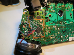
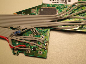
Here is the lower board all wired up. In the left image you can see where the hall sensor is connected to the 100-Ohm resistor. The hall sensor is the little black box in the lower third of the image wired to the grey cable and next to the red cable (which is my common ground contact for the entire assembly). For the other sensor remember that the hall sensor is mirrored and rotated so make sure you wire to the correct contact. I initially soldered to the wrong one and had to disassemble the controller during testing to fix it. All of the buttons are pull-down, meaning that they go to ground when they are “clicked”. This makes it easy, just use common ground for everything and you should be find. The hall sensors go to ground through a 100-Ohm resistor, probably to emulate the actual signal from the hall sensor when in the presence of the magnet in the trigger housing. It is not shown here, but all solder joints and wires were hot-glued in place after soldering to provide mechanical stability to the fragile wire-solder junctions during controller assembly and use.
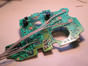
Upper board soldered. The bumper buttons are soldered to ribbon wires run under the board which you cannot see in this view. The bumpers are the contact switches shown on the top of the board in this view. There is another button (B-button) which is located on the lower board. I soldered a tag line to that button on the lower board and ran a cable-wire to the approximate location on the upper board. Then when the boards are reassembled in the controller’s plastic shell, I soldered and heat shrinked that single wire to pick up the “B” button on the upper board serial cable.
